
In an effort to encourage the increased use of all forms of model making during the process of design, a Month of Making was held throughout the 8 offices in Gensler’s South East Region. The idea was to jump start a culture of, exploration, discovery and investigation in ways that couldn’t be achieved with simply drawing, through the use of new tools available to the design process. Leading a small team that took responsibility for the digital design component of the exercise we developed several tracts for people to pursue that would expose them for specific design software and fabrication tools. The primary fabrication tools were the Laser Cutter, the CNC Machine and the 3D Printer. Additionally special software was created to enable existing Revit users to more easily produce advanced geometric shapes generally associated with Rhino using Grasshopper scripts.
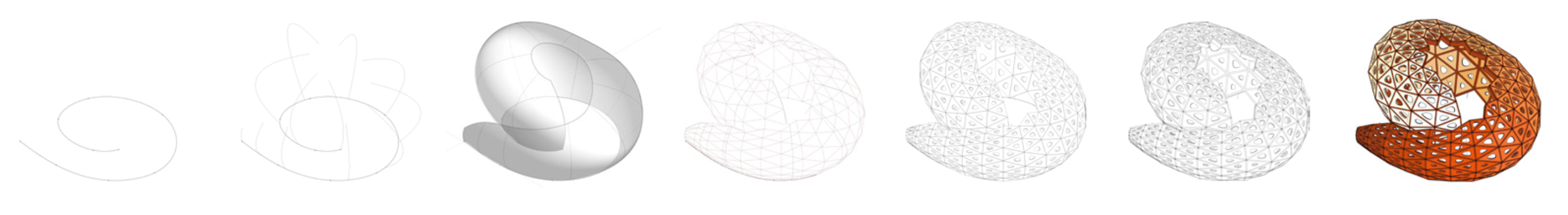
The development of a form over 7 steps, step 4 applies a triangular surface, 5 panelizes that surface, 6 & 7 apply instance properties for opening size and color with an in-house dynamo script.

Some of the results printed in 3D on a color capable 3D Systems Project 660 printer.

The same software approach was used to develop forms that were subsequently fabricated on one of either a 3d printer, Laser Cutter or CNC router. In the case of the Laser Cutter, 3D Forms where panelized, in folded and flattened, upon reassemble the original form is restored.
Design Execution Procedure (DEP)
The DEP is organized around a project delivery sequence from left to right. Each generalized task in the sequence is hierarchically broken down into a series of subtasks represented by nodes. Attached to the nodes is a detailed explanation of how to execute it. This is generally a short illustrated text, but could also be a link to a different format, or other resources that can aid in its execution. Additionally there are areas of the node graph that address how to manage the software & hardware demands on the project, the companies graphic and drafting standards, its libraries of standard components & details, and it's project filing protocol.
The system is managed through a mind map which facilitates organizing and linking the information graphically, and is subsequently published to a website specifically designed to enable the user to understand where they are in the overall process. This website is made available internally to Revit using the Revit API so that it becomes a form of online help to users of the program.
link